Convergent wedges and basal friction
This tutorial builds a convergent wedge, the fold-and-thrust belt or accretionary prism that grows where plates converge: a brittle layer pushed against a backstop, sliding on a weak decollement. It runs the same model twice, with a basal friction angle of 1° and of 5°, and compares how the wedge grows. The setup is a small version of the models of Lee, Tan & Chang (2024), cut down so that each run takes about 5 minutes on 4 threads. The first section explains the geology the model stands for.
| Dimension | 2D |
| Build | make ndims=2 usemmg=1 |
| Run time | about 5 minutes per run on 4 threads |
| Inputs | the wedge and ramp .cfg/.poly downloads and wedge_figures.py |
| Checked with | DynEarthSol 68cc2a0: widths and heights within 0.3 km of the table below |
What you will learn
- What convergent wedges are and where they form, what the backstop and the decollement are, and why basal friction sets the shape of a wedge
- How to set up a layered brittle model with
mattype_option = 1, no mesh file needed - How to push one wall over a fixed base without a velocity jump at the
corner (
vbc_x0 = 3withbottom_shear_zone_thickness), and howremeshing_option = 12keeps that wall vertical - How
inertial_scalingand the smallest element set the number of steps, and how to make a model cheap enough for a laptop - How to read thrust sequences from plastic strain and strain rate, and how basal friction sets the width and height of the wedge
- How to build a more complex geometry, two offset decollements, from a
.polyfile, and how their arrangement decides between ramp-flat thrusts and duplexes
Prerequisites
- ✅ DynEarthSol compiled in 2D with MMG,
make ndims=2 usemmg=1; see Build, Running DES3D and Adaptive mesh refinement with MMG. MMG refines the mesh along the faults as they form - ✅ A DynEarthSol version that includes
PR #113, which makes
remeshing_option = 12work. Without it the first MMG remesh scatters the mesh (see Troubleshooting) - ✅ Python 3 with
numpyandmatplotlibfor the plots, and optionally ParaView with2vtk.py; see Visualizing outputs - ✅ Read Part 1 of Tectonic rifting and subduction: this tutorial uses the same Mohr–Coulomb strain softening and the same output fields, and does not repeat them
The two configs and the plotting script are here:
wedge-phi1.cfg,
wedge-phi5.cfg and
wedge_figures.py.
The two configs differ only in modelname and the decollement friction angle.
For the two-decollement models of the last section:
ramp-gap8.cfg,
ramp-ov2.cfg,
ramp-ov14.cfg,
their ramp-gap8.poly,
ramp-ov2.poly and
ramp-ov14.poly,
and make_ramp_poly.py,
which writes a .poly file for any other arrangement.
Convergent wedges in nature
Where they form
Where two plates converge, the sedimentary rock on the lower plate is scraped off, shortened and stacked into a wedge that is thick at the back and thin at the front. This happens in two settings:
- Accretionary wedges, or accretionary prisms, at subduction zones: trench and ocean-floor sediments are scraped off the subducting plate and added to the front of the overriding plate. Examples are the Nankai margin of SW Japan, Cascadia, Barbados and the Makran, mostly under the sea.
- Fold-and-thrust belts at the front of mountain belts: the strata of a continental margin or a foreland basin are pushed ahead of the rising mountains. Examples are the Western Foothills of Taiwan, the Zagros of Iran and the Sub-Andes, and, no longer active, the Canadian Rockies and the Valley and Ridge of the Appalachians.
Mechanically the two are the same. Both are thin-skinned: the shortening is confined to the sedimentary cover above a fault, and the basement under that fault moves on undeformed. Dahlen (1990) compares a wedge to the sand or snow in front of a moving bulldozer.
Backstop and decollement
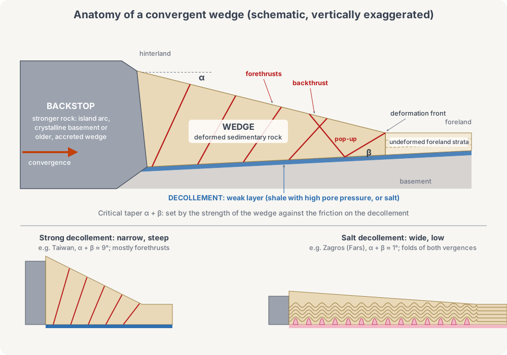
- The backstop is the stronger body behind the wedge that pushes it and passes on the plate convergence. In an accretionary wedge it is the crust of the overriding plate, often its volcanic arc, or the older and more lithified inner part of the prism; in a fold-and-thrust belt it is the metamorphic and crystalline core of the mountain belt, the hinterland. In Taiwan it is the Philippine Sea plate with the Luzon arc. In a sandbox experiment it is the moving wall, and in this tutorial it is the model's left wall.
- The decollement, or basal detachment, is the fault at the base of the wedge on which it slides over the basement. It follows the weakest layer in the sequence: shale or mudstone whose pore-fluid pressure approaches the weight of the rock above it, or evaporites (rock salt, gypsum). How strong it is, its friction, is what this tutorial varies.
- Inside the wedge, most of the shortening is taken up by forethrusts, which dip toward the backstop and carry rock toward the foreland. Fewer backthrusts dip the other way. A forethrust and a backthrust rooted at the same point of the decollement lift a pop-up between them. New thrusts usually break at the front, ahead of the older ones, and the frontmost active thrust is the deformation front.
Critical taper
The wedge's shape is measured by its taper: the slope α of its surface plus the dip β of the decollement. Pushed from behind, the wedge shortens and thickens until the taper reaches a critical value. A wedge at critical taper is on the verge of failure everywhere, slides on its base as a whole, and grows by adding new material at its front while keeping its shape (Davis, Suppe & Dahlen 1983; Dahlen 1990). The critical taper is set by how strong the decollement is compared with the rock of the wedge: the weaker the base, the lower the taper, and the wider a wedge built from the same amount of shortening.
Two active wedges show the range:
- Taiwan, a young collision of the Luzon arc with the margin of China, has α ≈ 3° and β ≈ 6° (Davis et al. 1983); the dip of its base is known from seismic profiles and deep wells drilled for oil. In the wells, pore-fluid pressure is two-thirds of the weight of the rock above, and its base has an effective friction coefficient of 0.12 to 0.20, a friction angle of about 7° to 11° (Dahlen 1990). Fast erosion balances the inflow of new material, so the mountain belt keeps a steady width of about 90 km. Forethrusts dominate.
- The Zagros in the Fars region of Iran slides on the Hormuz salt. Salt flows at a stress of only about 1 MPa, whatever its depth. Wedges over salt have a total taper of about 1°, and broad, symmetric folds with no dominant sense of vergence, because the largest compressive stress is almost parallel to the base (Davis & Engelder 1985; Dahlen 1990).
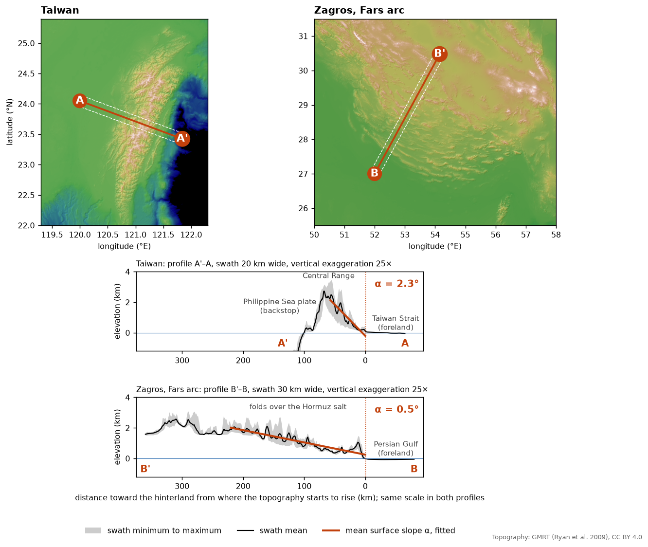
The profiles are drawn at the same scale with the backstop on the left, as in the model. Taiwan rises to 2.5 km within about 60 km of where its topography starts, a mean surface slope of 2.3°; the Fars climbs 2 km over more than 220 km, 0.5°. The swath mean smooths the topography, so it gives a slightly lower slope than the 3° of Davis et al. In the Fars map, the elongated ridges are individual anticlines over the salt, and folding continues offshore under the Persian Gulf.
This tutorial's model is a much simplified wedge. Its backstop is the left wall, its decollement a 1 km layer at a constant depth (β = 0), and it varies only the decollement's friction: 5° is still weaker than Taiwan's base, and 1° approaches a salt decollement.
How the model works
| Lee, Tan & Chang (2024) | This tutorial | |
|---|---|---|
| Domain | 450 km long | 40 km long |
| Brittle layer | 3, 6, 9 or 15 km | 3 km |
| Decollement | 1 km | 1 km |
| Push | 5 cm/yr, 100 km over 2 Myr | 5 cm/yr, 10 km over 200 kyr |
| Basal friction | 1° and 3° | 1° and 5° (3° is the exercise) |
| Surface diffusivity | 1e-6 and 1e-5 m²/s | 1e-6 m²/s |
| Run time | hours | about 5 minutes per run on 4 threads |
The materials are the paper's. The brittle layer softens from a friction
angle of 30° to 15° and a cohesion of 4 to 0.4 MPa over a plastic strain of
0.1; the decollement has the same cohesion but a friction angle of only 1° or
5°, held constant. Both have a density of 2600 kg/m³ and a shear modulus of
30 GPa. There is no temperature and no viscosity: rheology_type = elasto-plastic.
The basal friction is set as a material property of a 1 km layer, not as a
boundary condition. Shear on the base of the wedge is carried by that layer,
whose strength is cohesion + tan(φb) × normal stress; under 3 km of rock the
normal stress is about 80 MPa, so after softening the base resists about
1.8 MPa at φb = 1° and 7.2 MPa at φb = 5°.
Pushing a wall over a fixed base
The base is fixed (vbc_z0 = 3). If the left wall pushed at 5 cm/yr all
the way down, the node at the corner would have to move and stand still at
once. Instead vbc_x0 = 3 with bottom_shear_zone_thickness = 1e3 tapers the
push linearly from 5 cm/yr at the top of the decollement to zero at the base,
so the decollement next to the wall is sheared over its full thickness. Type 3
also fixes the vertical velocity on the wall, which keeps the wall nodes from
folding over each other.
The taper makes the foot of the wall lag its top, so between remeshes the
wall's lowest kilometre leans forward over a thinning sliver of decollement.
Left alone, after 10 km of shortening it would be a ramp 10 km long.
remeshing_option = 12 cuts the sliver off at every remesh and puts the wall
back to vertical at the position of its top.

What sets the cost
With the default quasi-static scheme, the time step is
dt = 0.5 × (smallest element height) / (push velocity × inertial_scaling)
so the number of steps for a given shortening does not depend on the push velocity:
steps ≈ 2 × shortening × inertial_scaling / (smallest element height)
Here that is 2 × 10 km × 3000 / 150 m = 400 000 steps on the initial mesh;
the run takes about 900 000, because MMG refines the faults to elements as
small as 80 m. The cost is set by three choices: shortening, inertial_scaling
and how small elements may get (resolution and smallest_size). The DES
default inertial_scaling = 1e5 would need 30 million steps; this tutorial
uses 3e3.
Is 3e3 enough for a quasi-static solution? DES solves the dynamic equations
with the density scaled up, and a smaller inertial_scaling lets inertia
matter more. Rerun with 1e4 to 100 kyr (3.4 times the steps) and the wedge is
the same to within 0.3 km of width and 0.1 km of height; the one difference is
that the second thrust breaks 10 kyr earlier, in the same place. When a
thrust nucleates is sensitive to small differences like this one, where it
breaks and the shape of the wedge are not, so do not read a 10 kyr difference
in thrust timing between two runs as a result.
Step 1: The configuration
[sim]
modelname = wedge-phi1
max_time_in_yr = 200000             # 10 km of shortening
output_time_interval_in_yr = 10000
has_output_during_remeshing = no
is_outputting_averaged_fields = no

[mesh]
meshing_option = 1                  # uniform box mesh
xlength = 40e3
ylength = 10e3                      # unused in 2D
zlength = 4e3                       # 3 km layer + 1 km decollement
resolution = 250
largest_size = 4
smallest_size = 0.2                 # tiny-element trigger; also the floor of dt
quality_check_step_interval = 1000
min_quality = 0.3
remeshing_option = 12               # restore the pushing wall (x0) to vertical

[control]
surface_process_option = 1
surface_diffusivity = 1e-6          # hillslope diffusion, m^2/s
inertial_scaling = 3e3

[bc]
# Left wall: pushes at 5 cm/yr (1.5844e-9 m/s), shear velocity fixed at 0.
# The push tapers linearly to 0 across the lowest 1 km (the decollement).
vbc_x0 = 3
vbc_val_x0 = 1.5844e-9
bottom_shear_zone_thickness = 1e3   # in m
# Right wall: free slip. Base: no slip.
vbc_x1 = 1
vbc_val_x1 = 0
vbc_z0 = 3
vbc_val_z0 = 0
has_winkler_foundation = no
has_water_loading = no
surface_temperature = 273
mantle_temperature = 273

[ic]
mattype_option = 1                  # horizontal layers
num_mattype_layers = 2
layer_mattypes = [0, 1]             # 0: brittle layer, 1: decollement
mattype_layer_depths = [0.75]       # interface at 0.75 * zlength = 3 km
weakzone_option = 0                 # no seed: the pushing wall starts the faults

[mat]
rheology_type = elasto-plastic
num_materials = 2
rho0 = [2600, 2600]
alpha = [0, 0]
bulk_modulus = [50e9, 50e9]
shear_modulus = [30e9, 30e9]
pls0 = [0, 0]
pls1 = [0.1, 0.1]
cohesion0 = [4e6, 4e6]
cohesion1 = [4e5, 4e5]
friction_angle0 = [30, 1]           # basal friction angle: 1 degree
friction_angle1 = [15, 1]
dilation_angle0 = [0, 0]
dilation_angle1 = [0, 0]
min_viscosity = 1e24                # unused by elasto-plastic, but required
wedge-phi5.cfg is the same file with modelname = wedge-phi5 and the
decollement angles set to 5:
friction_angle0 = [30, 5]
friction_angle1 = [15, 5]
Section by section:
[sim]runs 200 kyr, 10 km of shortening at 5 cm/yr, with a frame every 10 kyr, 0.5 km of shortening.[mesh]builds a uniform 40 × 4 km mesh.resolutionis not the element edge: the initial area limit is 1.5 ×resolution², and these settings give 2778 elements with a median edge of 364 m. At each remesh MMG refines where plastic strain accumulates, between the sizeslargest_sizeandsmallest_sizeallow. By 200 kyr the 1° run has 5850 elements: those in the faults (plastic strain above 1) have a median edge of 179 m, the rest 267 m.smallest_size = 0.2also remeshes when an element is squeezed below 0.2 of the area of an equilateral triangle with edgeresolution, which keepsdtfrom collapsing.[control]turns on hillslope diffusion of the surface and setsinertial_scaling, which with the element size sets the step count (see above).[bc]pushes the left wall, tapered across the decollement, against a free-slip right wall over a no-slip base.bottom_shear_zone_thicknessis in metres (--helpsaid km before PR #113). The Winkler foundation is off because the base is fixed, and water loading is off because the surface stays above sea level.[ic]makes two horizontal layers.mattype_layer_depthsis a fraction ofzlength, so 0.75 puts the top of the decollement at 3 km depth. No weak zone is needed: the first faults start at the corner of the pushing wall.[mat]has the brittle layer (index 0) and the decollement (index 1). The decollement friction is constant,friction_angle0 = friction_angle1, and its cohesion softens like the layer's.
The parameters you will change most often:
| Parameter | What it sets |
|---|---|
friction_angle0/1 (second entry) | Basal friction; the subject of this tutorial |
mattype_layer_depths, zlength | Layer and decollement thickness |
max_time_in_yr | Total shortening, at 0.05 km per kyr |
surface_diffusivity | How fast relief is smoothed |
resolution, smallest_size | Element size and the floor of dt; both change the cost |
inertial_scaling | Cost against how quasi-static the run is |
Step 2: Run
cd wedge                      # a directory holding the two configs
OMP_NUM_THREADS=4 /path/to/DynEarthSol/dynearthsol2d wedge-phi1.cfg
OMP_NUM_THREADS=4 /path/to/DynEarthSol/dynearthsol2d wedge-phi5.cfg
On an 8-core desktop (Intel i7-10700) the 1° run took 4.6 minutes alone on 4
threads, about 890 000 steps and 105 remeshes; the two at once on 4 threads
each took 5.5 minutes. On a 4-core laptop, run them one after the
other, or both at once with OMP_NUM_THREADS=2. The log prints a line every
100 000 steps, an Output # line every 10 kyr, and a Remeshing starts line
at every remesh. Output goes to wedge-phi1.save.* and wedge-phi5.save.*.
The same configs run on a plain Triangle build (make ndims=2). Triangle
remeshing does not refine, so the faults stay as wide as the initial elements
and the run is about 15 % faster. The wedges come out alike: at 200 kyr,
24.4 km wide and 2.0 km high at 1°, 15.7 km and 2.7 km at 5°, against 26.0
and 2.2, 15.6 and 2.8 with MMG. The third thrust at 1° breaks at 180 kyr
instead of 200.
Step 3: What to look for
export DES_DIR=/path/to/DynEarthSol   # where wedge_figures.py finds Dynearthsol.py
python3 wedge_figures.py . .
This writes the three figures below from the output in the current directory
and prints the wall position, thrust front and height of each frame. For
ParaView, convert with python3 /path/to/DynEarthSol/2vtk.py wedge-phi1.
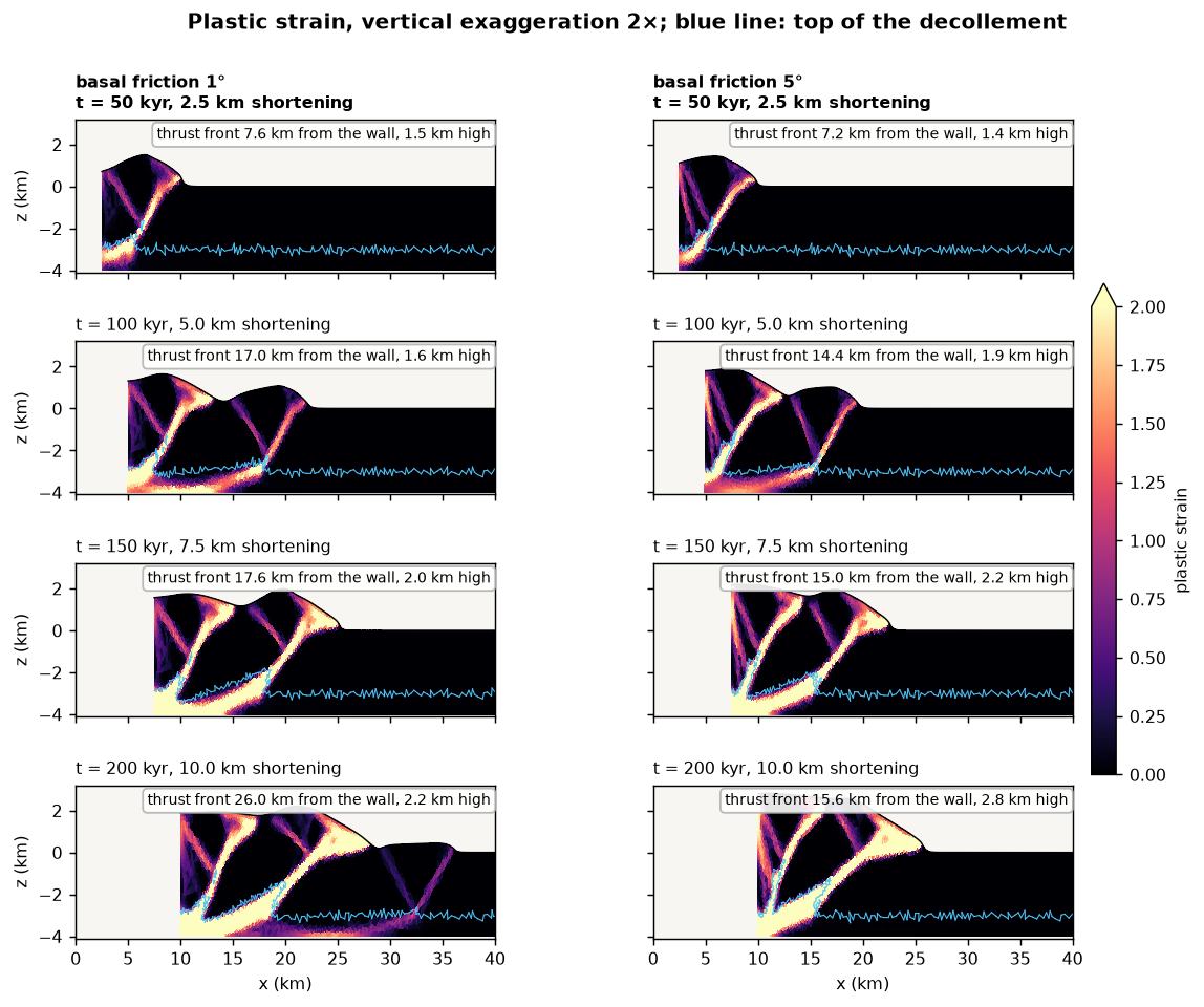
Plastic strain is where the faults are, or have been. Both runs start the same way. The corner of the pushing wall sheds a forethrust, dipping toward the wall, and a backthrust, dipping away from it, which together lift a pop-up of the layer next to the wall. Through the first 3.5 km of shortening the two runs are nearly indistinguishable: the basal friction does not matter yet, because the wedge is still too short for its base to carry much of the push.
Then they part:
- At 80 kyr both break a new thrust far ahead. At φb = 1° the new pair roots in the decollement 17 km from the wall; at φb = 5° only 15 km. The weak base transmits the push farther before the layer fails.
- At 200 kyr the 1° wedge has three thrust slices, the 5° wedge two. At 1° a third pair broke just before 200 kyr, 26 km from the wall; at 5° the second slice is still being overthrust and the front has hardly moved.
- The 5° wedge is narrower and higher. It is 15.6 km wide and 2.8 km high, against 26 km and 2.2 km at 1°. The same shortening has gone into less width and more height, a steeper taper.
- The decollement is dragged along. Under the wedge it is sheared and thickened against the wall (the bright band along the base); ahead of the wedge it stays undeformed.
| t (kyr) | Shortening (km) | Width at 1° (km) | Height at 1° (km) | Width at 5° (km) | Height at 5° (km) |
|---|---|---|---|---|---|
| 50 | 2.5 | 7.6 | 1.5 | 7.2 | 1.4 |
| 100 | 5 | 17.0 | 1.6 | 14.4 | 1.9 |
| 150 | 7.5 | 17.6 | 2.0 | 15.0 | 2.2 |
| 200 | 10 | 26.0 | 2.2 | 15.6 | 2.8 |
Width is measured from the wall to the thrust front, the farthest point of the upper 2.5 km of the brittle layer where plastic strain exceeds 0.5.
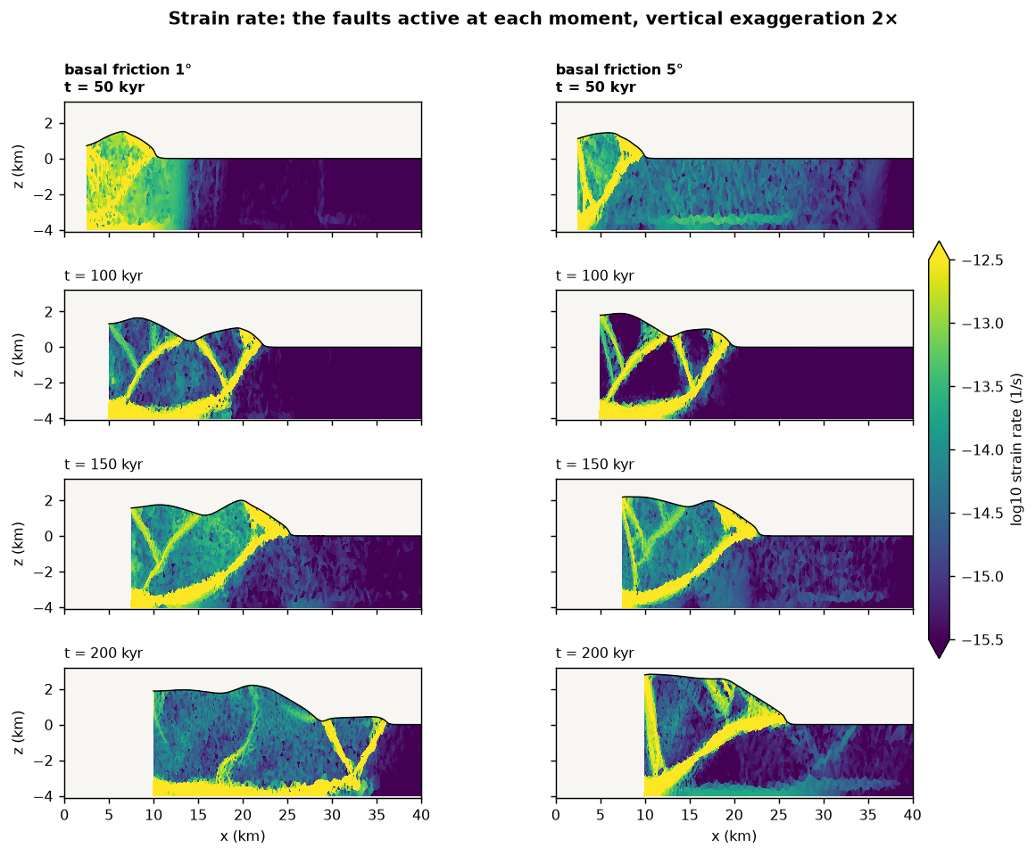
Strain rate shows which of those faults are moving at each moment, and it is fewer than plastic strain suggests. In both runs, from 80 kyr on, 75 to 94 % of the plastic strain rate of the brittle layer is within 8 km behind the thrust front, and the thrusts between the front and the wall are nearly locked. The runs differ in what carries the rest:
- At 1° the decollement does. It carries about half or more of all plastic strain rate, 49 to 79 %, and the wedge slides on it as a whole. The exception is the frame before the new thrust breaks (37 % at 180 kyr).
- At 5° the wedge itself does, more and more. The decollement's share falls steadily, from 63 % at 80 kyr to 39 % at 200 kyr, as the wedge grows and its base gets harder to slide. The backthrust at the wall takes up 7 to 15 % of the brittle-layer rate from 120 kyr on, against 2 to 6 % at 1° (14 % in the frame before the new thrust).
Lee, Tan & Chang (2024) found, over much longer runs, that the frontal thrusts are the only active structures for over 95 % of the time, and that new thrusts form and older ones reactivate in short episodes. Here the episodes are the jumps at 80 and 200 kyr.
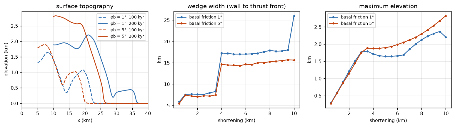
The width curve is a staircase: the front stays within about a kilometre while the wedge thickens behind it, then jumps forward by a thrust spacing when a new thrust breaks. The height grows while the front is stuck and pauses after each jump, when the push goes into the new thrust slice. At 1° the jumps are bigger and the height lower; that is the critical taper at work, a weaker base giving a lower taper.
Exercise: the paper's 3°
Copy wedge-phi1.cfg to wedge-phi3.cfg, set modelname = wedge-phi3 and
the decollement angles to 3, and run it. Then compare all three:
export DES_DIR=/path/to/DynEarthSol
python3 wedge_figures.py compare basal.png "wedge-phi1:φb = 1°" \
    "wedge-phi3:φb = 3°" "wedge-phi5:φb = 5°"
| Run | Width at 200 kyr | Height at 200 kyr | New thrusts after the first |
|---|---|---|---|
| φb = 1° | 26.0 km | 2.2 km | at 80 and 200 kyr |
| φb = 3° | 22.2 km | 2.4 km | at 80 and 200 kyr |
| φb = 5° | 15.6 km | 2.8 km | at 80 kyr |
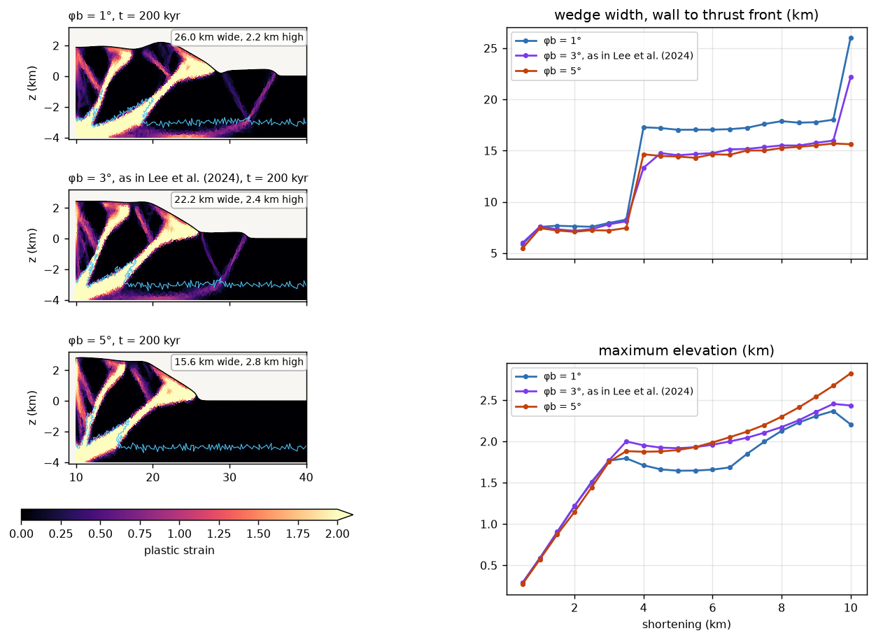
At 3° the wedge follows the 5° one at first: the second thrust breaks 13 to 15 km from the wall, as at 5°, and the height between jumps is in between. But just before 200 kyr it breaks a third thrust, at the same time as the 1° wedge. Over only 10 km of shortening the wedge has room for two or three slices, so a difference in basal friction shows up as whether one more thrust has formed or not. That is why the main comparison uses 5°: over this short a run, 3° and 1° end up looking alike. In the paper's 100 km runs, 1° and 3° differ clearly.
More complex geometry: two decollements
A real wedge seldom slides on one flat decollement. A sedimentary sequence
often holds several weak layers at different depths, each of limited extent,
and a thrust that runs out of one has to climb to the next. Feng, Bartholomew
& Choi (2015) used DynEarthSol to show that the arrangement of two
decollements, how far they overlap or how wide the gap between them is,
decides the style of the thrust system. A long overlap gives a duplex, a short
gap or overlap a ramp-flat thrust. DES handles such geometry with the same
physics: draw the layers in a .poly file instead of layering them with
mattype_option = 1 (see
Making a complex mesh with .poly file). The models
below follow the idea of that paper, not its setup, and keep this tutorial's
materials and boundary conditions.
The geometry

The box is 5 km deep. The lower decollement is the bottom 1 km from the
pushing wall to x = xa; the upper one lies between 1.5 and 2.5 km depth from
x = xb to the right wall. Both have the 1° friction of wedge-phi1.cfg, and
the rest is the same brittle layer as before. Beyond xa the bottom of the
layer is welded to the fixed base, so the push has to find another way
forward. The three runs differ only in xa and xb.
The configuration and the .poly file
Starting from wedge-phi1.cfg, three things change: the mesh comes from a
.poly file, the box is 5 km deep, and the materials come from the file's
regions instead of from layers:
[mesh]
meshing_option = 90                 # mesh from a .poly file
poly_filename = ramp-ov2.poly
zlength = 5e3

[ic]
mattype_option = 0                  # materials from the .poly regions
weakzone_option = 0
num_mattype_layers, layer_mattypes and mattype_layer_depths are dropped,
and [mat] is unchanged: material 0 is the brittle layer, material 1 a
decollement. bottom_shear_zone_thickness = 1e3 still matches the lower
decollement at the wall. The .poly file lists the corner nodes, the segments
between them with their boundary flags (1 left, 2 right, 16 bottom, 32 top, 0
inside), and one point in each region with its material and largest element
area, here 1.5 × 250² m² to match the uniform mesh:
#### node coordinates ####
# npoints ndims 0 0
  11 2 0 0
   0        0.0        0.0
   1        0.0    -4000.0
   2        0.0    -5000.0
   3    16000.0    -5000.0
   4    40000.0    -5000.0
   5    40000.0    -2500.0
   6    40000.0    -1500.0
   7    40000.0        0.0
   8    16000.0    -4000.0
   9    14000.0    -2500.0
  10    14000.0    -1500.0
#### segments ####
# nsegments 1
  13 1
   0  0  1  1
   1  1  2  1
   2  2  3 16
   3  3  4 16
   4  4  5  2
   5  5  6  2
   6  6  7  2
   7  7  0 32
   8  1  8  0
   9  8  3  0
  10  9  5  0
  11 10  6  0
  12  9 10  0
#### holes, must be 0 ####
0
#### regions ####
# nregions
  3
# k  xk  zk  mattype  size
  0     8000.0    -4500.0 1 93750
  1    27000.0    -2000.0 1 93750
  2     1000.0     -500.0 0 93750
make_ramp_poly.py 16 14 ramp-ov2.poly writes this file; any other xa and xb
give another arrangement. The internal segments shape only the initial mesh:
with MMG, DES keeps no internal segments (is_discarding_internal_segments = yes), and markers carry the materials, so the decollements can deform and
fold.
Run and plot
for c in gap8 ov2 ov14; do
    OMP_NUM_THREADS=4 /path/to/DynEarthSol/dynearthsol2d ramp-$c.cfg
done
export DES_DIR=/path/to/DynEarthSol
python3 wedge_figures.py sections ramp.png 8,16 "ramp-gap8:gap of 8 km" \
    "ramp-ov2:overlap of 2 km" "ramp-ov14:overlap of 14 km"
The runs start with about 3600 elements and take about 720 000 steps to 160 kyr, 8 km of shortening. The three run together on 3 threads each took 9 to 9.5 minutes on the 8-core desktop. They stop at 160 kyr because by 180 kyr the front of the 2 km overlap run reaches the right wall.
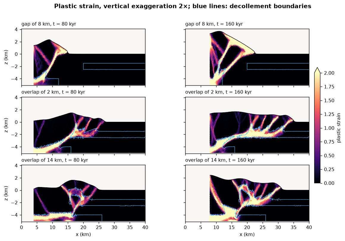
The three arrangements give three styles:
- 8 km gap: thrusts at the end of the lower decollement. The thrusts root where the lower decollement ends, at x = 12 km. Beyond it the base is strong, so the wedge grows steep: 3.7 km high at 160 kyr, with its front at x = 22.5 km, just reaching the upper decollement. Only later does deformation step onto the upper decollement, and the front jumps to 27 and then 34 km by 200 kyr.
- 2 km overlap: a ramp-flat thrust. The fault leaves the lower decollement near its end, climbs 1.5 km of rock in a ramp to the upper decollement, and follows that flat forward, with imbricate splays branching up from it. The wedge stays low and wide: 1.7 km high, front at x = 35 km.
- 14 km overlap: a duplex-like stack. The ramp cuts up from the lower decollement at about x = 16 km, some 10 km before its end. The slice of rock between the two decollements is carried up the ramp, and the upper decollement folds over it as a roof: 2.4 km high, front at x = 31 km.
The 2 km and 14 km runs match the styles Feng et al. found for short and long overlaps. The same shortening on the same materials builds a wedge from 1.7 to 3.7 km high, depending only on where the weak layers are.
Troubleshooting
All rows were observed while building this tutorial.
| Symptom | Cause and fix |
|---|---|
After the first remesh, dt jumps to about 5e5 yr and the run ends at once, with prepare_interpolation warnings | An MMG build of DynEarthSol without PR #113, where remeshing_option = 12 scatters the mesh. Update DynEarthSol |
| The node count drops by half at the first remesh and plastic strain is spread over the whole wedge, with no discrete thrusts | A build without MMG and without PR #113: each remesh deletes interior nodes. Update DynEarthSol |
Error: tangled mesh (post-remesh): boundary segments ... cross on the pushing wall | The push was tapered with vbc_x1 = 1 and the vbc_val_x1_ratio* table, which leaves the vertical velocity of the wall free; the wall folds over itself in the decollement. Push from the left wall with vbc_x0 = 3, which fixes it |
dt falls tenfold within 60 kyr, with size of element ... too small near the base of the pushing wall | remeshing_option = 11 instead of 12: the sliver under the slanted wall foot is never cut off, and its elements keep shrinking |
| Strain diffuse even with the fix | The mesh is too coarse: thrusts need several elements across the 3 km layer. Keep resolution at 250 or below, which starts at edges of about 360 m and lets MMG refine the faults to about 180 m |
| The run takes much longer than 5 minutes | inertial_scaling left at the default 1e5 (33 times the steps), or smallest_size lowered |
Next steps
- Make the layer thicker: the paper finds the front advances about 6 km/Myr
faster for each extra kilometre of layer. Raise
zlengthandmattype_layer_depthstogether so the decollement stays 1 km thick, and expect a longer run - Fill the foreland with sediment:
surface_process_option = 102adds simple deposition to the diffusion - Couple a landscape-evolution model with GoSPL
References
- Davis, D., Suppe, J. & Dahlen, F. A. (1983). Mechanics of fold-and-thrust belts and accretionary wedges. J. Geophys. Res., 88, 1153–1172.
- Feng, L., Bartholomew, M. J. & Choi, E. (2015). Spatial arrangement of décollements as a control on the development of thrust faults. J. Struct. Geol., 75, 49–59. doi:10.1016/j.jsg.2015.03.002
- Dahlen, F. A. (1990). Critical taper model of fold-and-thrust belts and accretionary wedges. Annu. Rev. Earth Planet. Sci., 18, 55–99.
- Davis, D. M. & Engelder, T. (1985). The role of salt in fold-and-thrust belts. Tectonophysics, 119, 67–88.
- Lee, F.-Y., Tan, E. & Chang, E. T.-Y. (2024). Numerical modeling of fault-and-thrust belt stress evolution. Front. Earth Sci., 12, 1415139. doi:10.3389/feart.2024.1415139
- Ryan, W. B. F. et al. (2009). Global Multi-Resolution Topography synthesis. Geochem. Geophys. Geosyst., 10, Q03014. Topography in the maps above, from GMRT, CC BY 4.0.
- Choi, E., Tan, E., Lavier, L. L. & Calo, V. M. (2013). DynEarthSol2D: an efficient unstructured finite element method to study long-term tectonic deformation. J. Geophys. Res. Solid Earth, 118, 2429–2444.